Slanted compartment

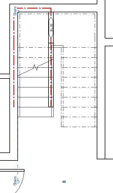
Go to a view where the slanted compartmentation should be. Create a reference plane and name it. In this example the reference plane name is “Stairs”.
Go to Architecture → Ref Plane
Draw the line by one of the walls.
Note: Make sure reference planes are visible in the view.
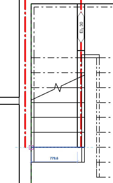
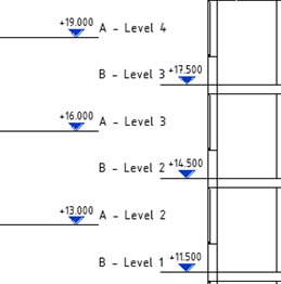
Measure the width of the compartmentation in the floor plan, the stairs in this case.
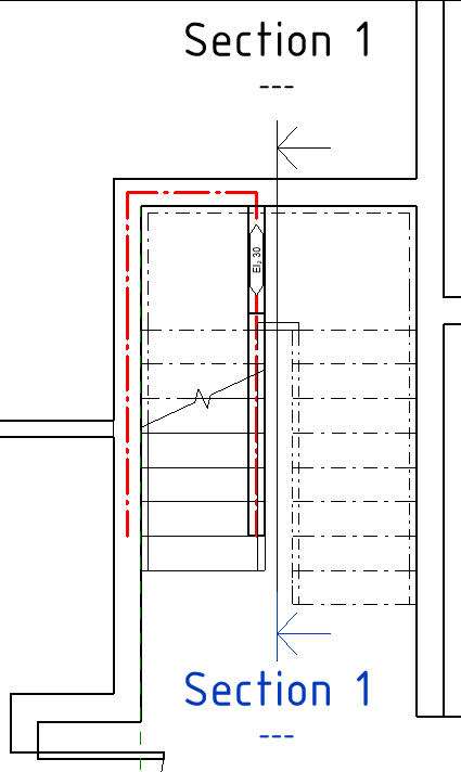
Draw a section parallel to the slanted compartmentation.
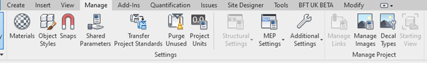
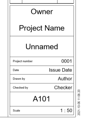
Change logo in the upper right corner. Go to Manage tab → Manage Images
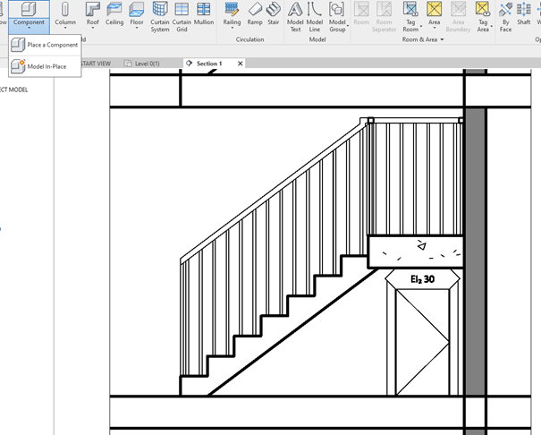
Go to section and start creating a Model In-Place.
Architecture → Component → Model in-place
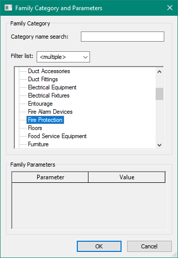
Select Generic Model (Revit 2020-2021) or Fire Protection (2022- )
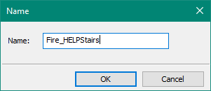
Name the new family fitting to the project.
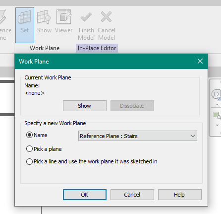
Choose the Work Plane to Stairs in the drop down.
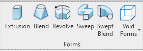
Create an extrusion
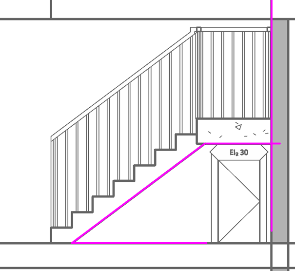
Use Pick Line and select the wall, under of the stair and top of the floor
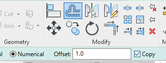
Use offset tool and offset the lines under the stairs with 1mm.
Note: Make sure Copy is enabled.
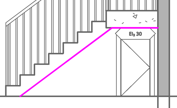
Use trim corners to finish the sketch.
Note: It is necessary to zoom very close to the ends.
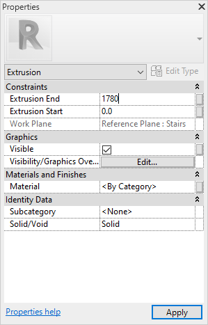
In Properties, type the width of the stair / ramp + 1000mm in one of Extrusion End/Start.
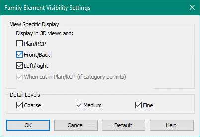
In Visibility / Graphic override, remove Plan / RCP
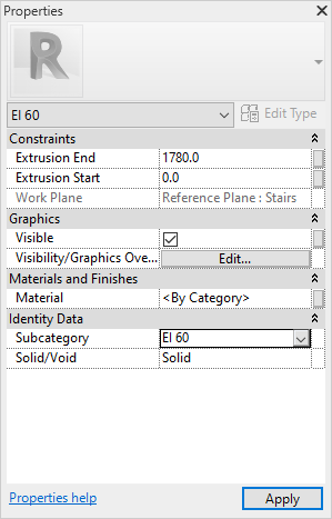
Under Subcategory, select the correct requirement.
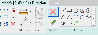
Finish the sketch.
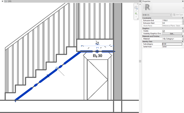
If you see the boundary in the section. The extrusion grows in the correct direction. If not, change the value to negative Stair width.
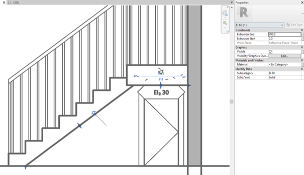
In this scenario it is ok so change Extrusion End to the correct width.
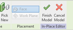
Finish the Model