Titleblocks

How to transfer titleblock from a linked model into the enginering model

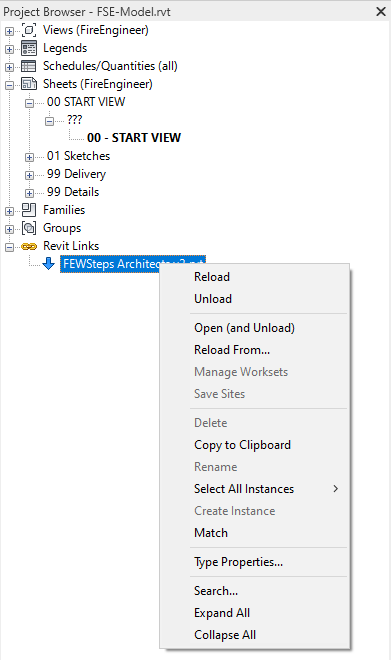
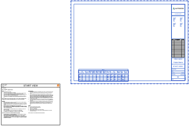
In the Revit session with the model open the linked file with the Titleblock and Titleblock information.

In the project browser, Open and unload the file.
This so it is possible to transfer Titleblocks between the two files.
Compared to AutoCAD it’s not possible to have a model loaded as a link and have the file open in the same session in Revit.

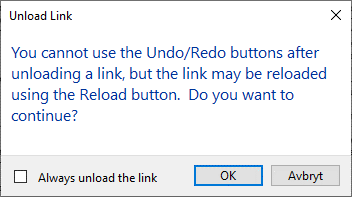
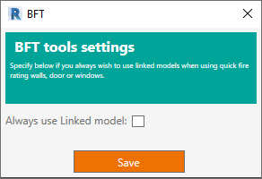
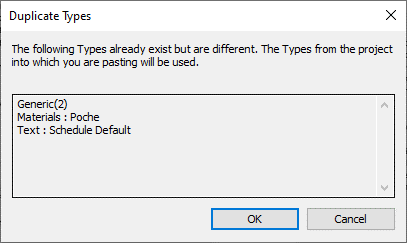
Press ok to continue.

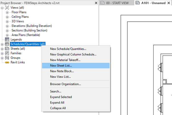
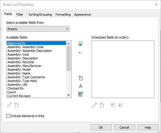
Create a new sheet list.

Now it becomes more difficult because this will be different in each project almost.
In the left Field column find the parameters that is specific for this project.
Contact the BIM Coordinator of the project if necessary
Not recommended: It is possible to move all to the right column. But this will copy several parameters that never going to be used.
Finish with ok.

Give the schedule a unique name  and drag and drop the schedule onto a sheet.

Select both the schedule and titleblock, use copy to clipboard.

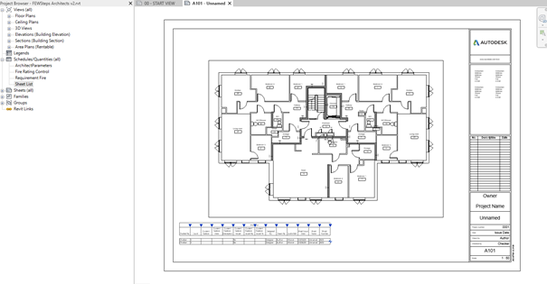
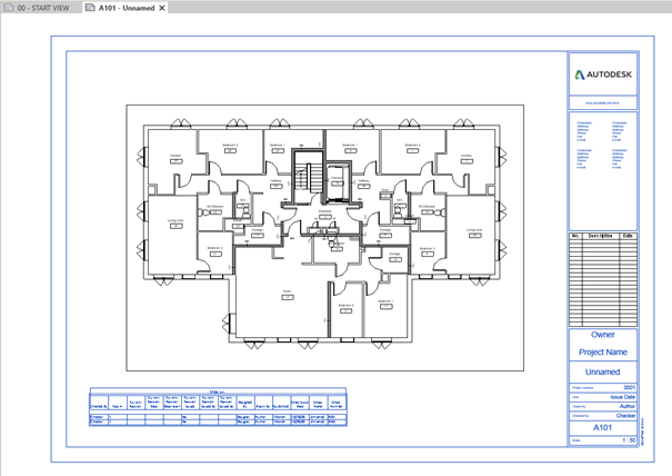
Jump back to the enginering model and paste them both in a sheet view.

The notification tells that it already exist some of the information being pasted and it will use the enginering model’s settings.

Delete them after pasting.
This will have copied all the different Sheet specific parameters with the schedule, and the correct titleblock that should be used in the project are now copied to the engineer model.
After the titleblock is copied with the sheet parameters to the model, next step is to copy the placement of the views on the sheet.
Go back to the linked model, and control if there exist a Guide Grid in the sheet view that seems to be used in the project.
In this scenario there exist no Guide Grid, but if there existed already some Guide Grids the workflow below still works.
Start by checking if there is a Reference Plane/two grids crossing each other in the model.
Note: Turn on not in the sheet view but in the floor plan view.
If there is none, or there are so many that there are no logic, just create a new one under Architecture → Ref Plane.
Draw a small line, vertical or horizontal (can’t be oblique).
Note: the horisontal green line(Ref Plane) in the bottom left.
Go back to the sheet view.
Create a new Guide Grid,  View → Guide Grid
Enter a name that is easy to recognize.

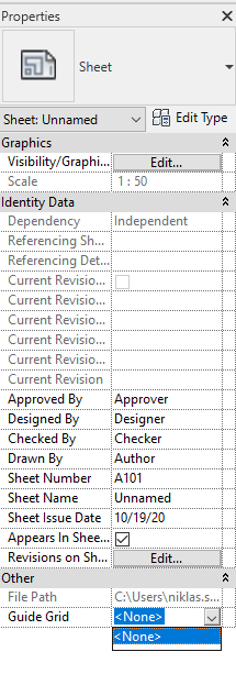
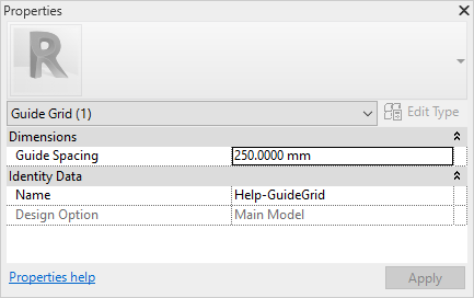
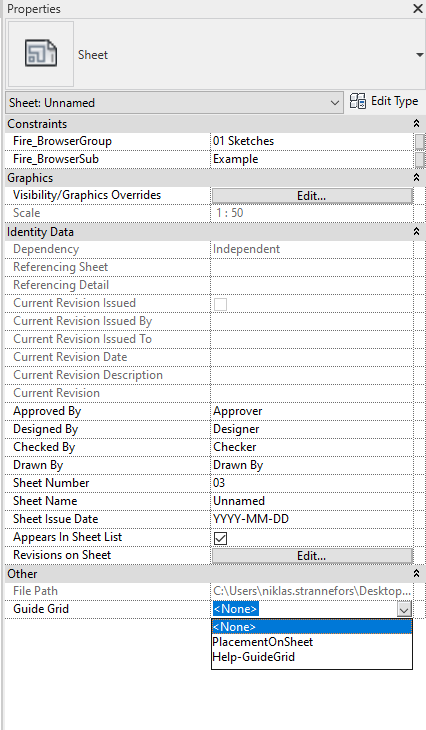
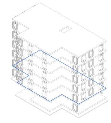
Select the new “blue” grid that is created in the sheet view, and change in Properties Guide Spacing from 250.000 mm to 25 mm

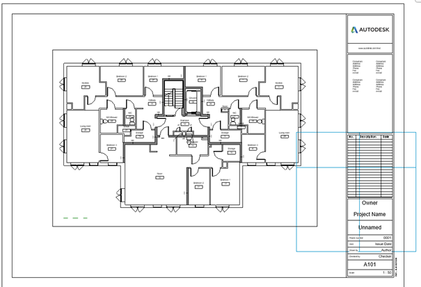
Use the drag ends to make the grid smaller, having only one intersection left

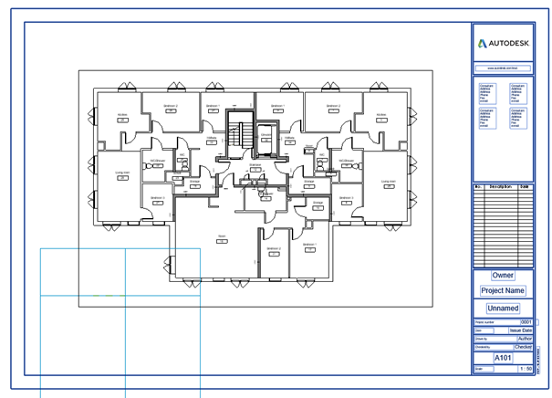
Start the Move command under Modified → Move.

Snap to the intersection in the grid, and move it to an end of the Ref Plane.

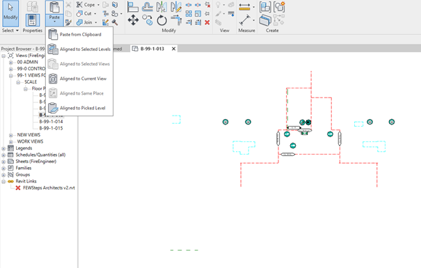
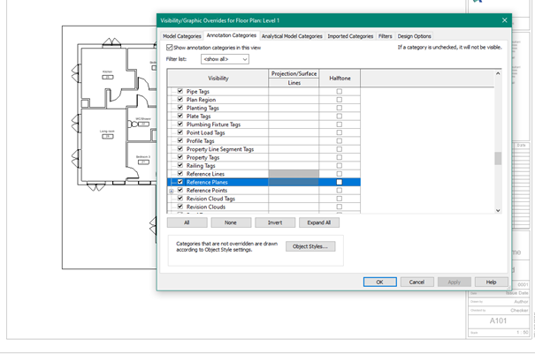
Select the Ref Plane in the linked model, use Copy to Clipboard and go back to the model.

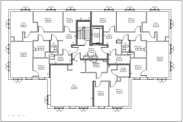
Paste align to current view in a floor plan, it will now have the same position in the engineer model.

Some of the parameters that are used on sheets are project specific.

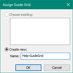
To transfer the parameters and Guide grid from the linked file to the model will be copied by using Transfer Project Standards.

Manage → Transfer project Standards

Check none and then select:

  • Guide Grid
  • Project Info

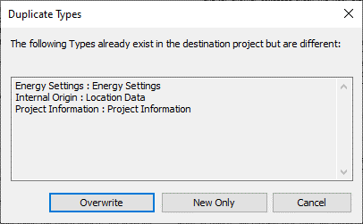
Same as before, just select overwrite.

Close the tab with the open linked model, don’t save.

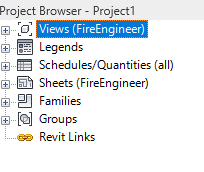
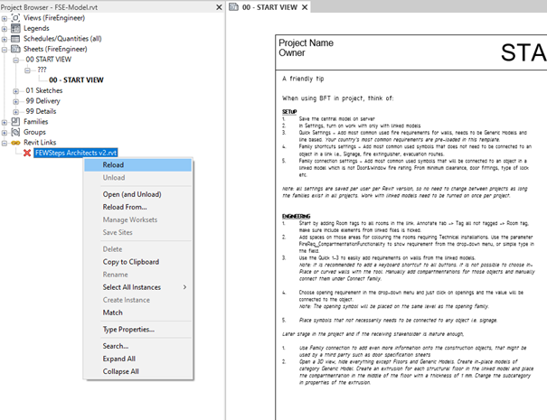
Reload the link in project browser.

Enable Guide Grid on the sheet views in the model and drag and drop Floor plans onto them.
Use the Move command, Modifty → Move and snap same end of the Ref Plane and move the view to the intersection of the Guide grid.
Back to help